
HYDRAULIC CLAMPING AND LIFTING
Hydraulic Clamping and Lifting
- Hydraulic Cylinder Style Clamps (Nut Clamps)
- Hydraulic Fixed Clamp Height Rocker Clamps (Ledge Clamps)
- Hydraulic Adjustable Clamp Height Rocker Clamps (Narrow Ledge Like Clamps)
- Hydraulic Fixed Clamp Height Sliding Clamps (C Clamps)
- Hydraulic Die Lifters/Rollers
- Hydraulic Control Units (Hydraulic Pump/Valves for Clamps and Lifters)
- Pneumatic Die Lifters (Air Bag Lifters)
- Mechanical ¼ Turn Set Clamps (Quick Set Clamps)
- Mechanical Portable Hand operated Die Lifters
- Mechanical (Stationary) Spring loaded Die Lifters/Rollers
- Mechanical Spring Loaded Ball Cartridges
- Swing Away Bolster Extensions
- Lift Off Bolster Extensions
- Detachable Heavy Duty Bolster Extensions with Legs
- Traveling and Slotless Bolster Extensions
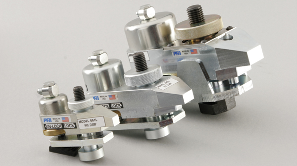
Hydraulic Nut Clamps
WHEN TO USE NUT CLAMPS:
Use Nut Clamps with dies having slotted die plates and enough clearance for the Nut Clamp body (see chart). U-Slot brackets or ears may also be added to dies in some applications.
If systems are setup to have hydraulics removed during stamping, Hydra Mechanical (L style) clamps (with a mechanical lock) should be selected. If a dedicated hydraulic system is considered, the Fully Hydraulic clamps (with either multiple upper zone control or check valves) may be the preferred choice.
Clamp model and quantity should be selected to provide a total clamping force greater than the total (static and dynamic) force applied to the system during use.
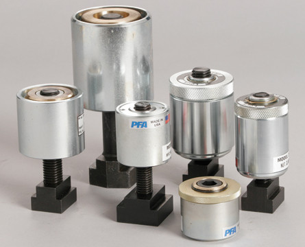
HOW THEY WORK:
Nut Clamps are moved into position in a slot in the die plate (gaps between clamp and die/slot allow movement). When hydraulic pressure is applied, the clamp pulls upward on the T-bolt and the clamp body moves downward to clamp the plate. Hydraulic pressure is maintained during operation, or the Locking Nut (L style) is engaged to allow removal of clamp hydraulic pressure during stamping. To unclamp, hydraulic pressure is removed and clamps open under internal spring force. (Note: Reapplication of hydraulics is required to unlock the Locking Clamps (L) prior to releasing pressure and unclamping).
Hydraulic Ledge Clamps
WHEN TO USE FIXED CLAMP HEIGHT ROCKER CLAMPS
Use Fixed Clamp Height Rocker Clamps with dies having an open ledge clamp plate or a slot in the die large enough to accommodate the clamp nose for full clamp engagement. Ledge brackets, bars, or ears may also be added to dies in some applications to accommodate the clamps and/or plates milled to set a common clamp height.
If systems are setup to have hydraulics removed during stamping, Hydra Mechanical (L style) clamps (with a mechanical lock) should be selected. If a dedicated hydraulic system is considered, the Fully Hydraulic clamps (with either multiple upper zone control or check valves) may be the preferred choice.
Clamp model and quantity should be selected to provide a total clamping force greater than the total (static and dynamic) force applied to the system during use.
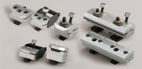
HOW THEY WORK:
Ledge Clamps are moved into position with the lower body stop set against the die plate (gaps between clamp and die/slot allow movement) or may be permanently mounted on one side to act as a side stop.
When hydraulic pressure is applied, the clamp nose moves downward onto the plate, clamping the die. Hydraulic pressure is maintained during operation, or the Locking Nut (L style) is engaged to allow removal of clamp hydraulic pressure during stamping. To unclamp, hydraulic pressure is removed and clamps open under internal spring force. (Note: Reapplication of hydraulics is required to unlock the Locking Clamps (L) prior to releasing pressure and unclamping).
Hydraulic Adjustable Rocker Clamps
WHEN TO USE ADJUSTABLE ROCKER CLAMPS:
Use Adjustable Rocker Clamps with dies having a cutout clamp position, narrow slot in the die or for typical clamp plate applications with variable clamp plate thickness across several dies. Also, ledge brackets, blocks, bars, or ears may be added to dies in some applications to accommodate the clamps and/or small slots cut into the dies to accept the smaller clamp nose.
If systems are setup to have hydraulics removed during stamping, Hydra Mechanical (L style) clamps (with a mechanical lock) should be selected. If a dedicated hydraulic system is considered, the Fully Hydraulic clamps (with either multiple upper zone control or check valves) may be the preferred choice.
Clamp model and quantity should be selected to provide a total clamping force greater than the total (static and dynamic) force applied to the system during use.

HOW THEY WORK:
The Adjustable Rocker Clamps are moved into position with the lower body stop set against the die plate (gaps between clamp and die/slot allow movement).
The center height adjustment knob is turned clockwise until the nose of the clamp touches the clamp plate.
When hydraulic pressure is applied, the clamp nose moves downward onto the plate, clamping the die. Hydraulic pressure is maintained during operation, or the Locking Nut (L style) is engaged to allow removal of clamp hydraulic pressure during stamping. To unclamp, hydraulic pressure is removed and clamps open under internal spring force. (Note: Reapplication of hydraulics is required to unlock the Locking Clamps (L) prior to releasing pressure and unclamping). After the clamp is released, the adjustment knob is turned to further open the clamp, as desired.
Hydraulic C Clamps
HYDRAULIC, FIXED CLAMP HEIGHT, SLIDING STYLE C CLAMP
“C” Clamps work in similar applications to our fixed height ledge clamps, but provided a different profile and customer preference. Using small Bolt-on guides, these clamps also work well in “slotless” press applications (bolsters with threaded holes only). Also, by reaching under and over the clamping plate and providing multiple ports, the clamp can be set “deeper” over the plate if needed, resulting in a lower installed profile.
Available in the single piston style Model 283 and double piston style Model 283D, “C” clamps require only 1.25″ to 1″ of die plate engagement, respectively, and may be modified at the nose to engage plates that have been pocketed to match clamp heights. Ledge brackets, bars, or ears may also be added to dies in some applications to accommodate the clamps. Clamp model and quantity should be selected to provide a total clamping force greater than the total (static and dynamic) force applied to the system during use.
Clamp sizing is done to provide a minimum .060″ clearance to the clamp plate and accommodate a wide range of slot neck height and clamp plate height combinations. For a given T-slot neck depth (N) and clamping plate height (CLH) the needed part number can be easily determined.
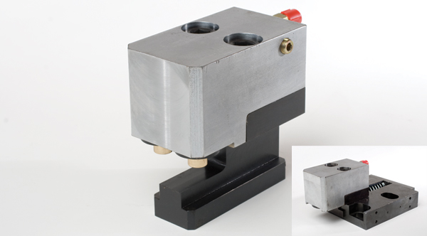
Hydraulic Die Lifters/Rollers
WHEN TO USE HYDRAULIC DIE LIFTERS:
Use hydraulic die lifters when die weights are typically standard for medium to large presses. Dies with a small footprint relative to the die weight will typically require Hydraulic Die Lifters.
In addition to a large lifting force, hydraulic actuation allows for easy and controlled movement of the die only when desired, in contrast to spring loaded lifters, typically used in light die applications.
Inline rollers provide for movement along the rail and transverse rollers for movement 90 degrees to the slot direction. Ball roller rails allow for movement in any direction but are generally more limiting in overall die weights.
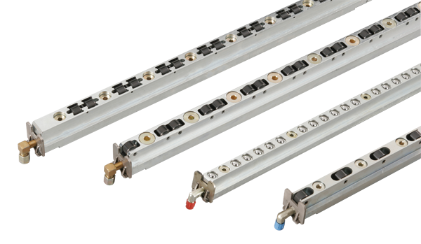
HOW THEY ARE USED:
Hydraulic Die Lifter Rails are secured in the slots via the included mounting bracket. Stand offs ensure the rails are captured in the slots, yet move freely up and down prior to die insertion.
The rails are activated using a PFA Hydraulic Control Unit, placing them in the “lifted” position. The die is then inserted by “rolling” into the press and lowered by rotating the control valve to the “lower” position (venting pressure). After insertion, the die may be indexed into position using an additional pair of transverse rollers lifting the die, alternating use of the transverse lifters and inline lifters, using a single pair of ball roller rails, or by other means.